Screw diameter / L/D ratio
The screw is the heart of the blown film extruder, and its diameter (measured in mm) and length-to-diameter (L/D) ratio are two of the most important design parameters. Screw diameter determines the maximum output capacity – larger diameters provide higher throughput because they have larger cross-sectional area for melt flow. Common screw diameters for blown film range from 30 mm (small pilot lines) up to 200 mm (high-output industrial lines). The output scales roughly with the square of the diameter, so a 150 mm screw can produce about 4 times more than a 75 mm screw. The L/D ratio is the ratio of the screw's effective length to its diameter; typical values for blown film are 24:1 to 32:1, with modern high-performance lines using 30:1 or 36:1. A higher L/D ratio provides more melting length, allowing better mixing, lower melt temperature, and higher output due to longer residence time for heat transfer. However, longer screws are more expensive, require more torque, and may cause degradation for heat-sensitive materials if residence time is excessive.
The selection of screw diameter and L/D ratio must match the required output, the resin type, and the film properties. For high-output lines (500+ kg/h), a diameter of 120 mm or larger is typical, with L/D of 30:1 to 32:1. For lower outputs (100-300 kg/h), diameters of 75-90 mm with L/D 28:1 are common. For specialty resins like PA or EVOH, which are heat-sensitive, a shorter L/D (24:1) with gentle screw design is preferred to avoid degradation. For HDPE, which has high crystallinity, a longer L/D (30:1) with a barrier screw is beneficial to achieve complete melting. The screw geometry also includes the compression ratio (ratio of feed to metering channel depth), which affects shear and mixing. Typical compression ratios range from 2.5:1 to 4.0:1. Barrier screws (with a secondary flight) improve melting efficiency and output by separating melt from solid bed; they are often used for high-output blown film. Additionally, the screw may have a mixing section (e.g., Maddock or pineapple) at the end to homogenize temperature and color. The choice of screw design is often tailored by the manufacturer based on the specific resin and application.
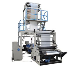
Blown Film Machine
Key performance indicators related to screw diameter and L/D include specific output (kg/h per RPM), melt temperature rise, and pressure stability. Larger diameter screws require higher motor torque; the gearbox must be rated accordingly. The L/D ratio affects the residence time – longer L/D increases residence time, which can improve mixing but may cause thermal degradation for some materials. For recycled materials with contaminants, a longer L/D with venting capability is used to remove volatiles. The screw speed range is typically 30-150 RPM; higher speeds increase output but also shear heating, which may require additional cooling. The barrel is usually divided into zones (4-6) for temperature control; the feed zone is cooled, the compression and metering zones are heated. Proper temperature profiling depends on the screw design – a barrier screw may require different settings than a conventional screw. Maintenance involves periodic pull-out to check screw wear – a worn screw reduces output and increases melt temperature. Hardfacing (e.g., tungsten carbide) is applied to screws processing abrasive materials (with fillers).
When selecting a screw for a new blown film line, consider the target output, the range of resins to process, and the desired film quality. A larger diameter with high L/D offers flexibility but at higher cost. Some extruders are designed with interchangeable screws to process different materials – e.g., a general-purpose screw for LDPE/LLDPE and a specialized screw for HDPE. The screw should be matched with the barrel material – bimetallic barrels (with a wear-resistant liner) are recommended for highly filled or recycled materials. The screw's compression ratio and flight geometry must be optimized to avoid surging (output fluctuations) and melt fracture. Many suppliers use simulation software to design screws for specific applications. In operation, the screw speed is adjusted to achieve the required output, and the melt temperature is monitored – if too high, reduce screw speed or adjust barrel cooling. Regular cleaning and purging with appropriate compounds prevent carbon buildup. Ultimately, screw diameter and L/D ratio are foundational choices that determine the line's capacity, efficiency, and product quality; they must be carefully evaluated during the equipment selection phase to ensure long-term success.
