Film thickness range (microns)
The film thickness range for blown film products spans from ultra-thin (5-15 microns) for high-speed packaging and liners, up to heavy gauge (200-300 microns) for industrial geomembranes and construction sheets. Measured in microns (µm) or gauge (1 mil = 25.4 µm), thickness is one of the most critical quality attributes because it directly affects material cost, mechanical strength, optical properties, and sealing performance. The achievable thickness range depends on the die gap, blow-up ratio (BUR), draw-down ratio (DDR), extruder output, and line speed. In general, a blown film line can produce films from about 10 µm to over 250 µm with appropriate screw and die designs. However, producing very thin films (below 10 µm) requires high melt strength, stable bubble, and precise cooling to avoid tearing; LLDPE and LDPE blends are often used. Very thick films require lower line speeds and higher outputs, and may need post-cooling to avoid blocking.
Typical thickness ranges by application: 10-25 µm for grocery bags, produce bags, and light packaging; 25-50 µm for trash bags, liners, and shrink films; 50-100 µm for agricultural mulch, silage, and industrial covers; 100-200 µm for heavy-duty sacks, geomembranes, and tarpaulins; 200-300 µm for pond liners and construction vapor barriers. The choice of thickness is also influenced by regulatory standards – e.g., food contact films must meet minimum thickness for barrier properties. Thickness uniformity across the width is crucial; variations above ±10% can cause weak spots, seal failure, and excessive material usage. Therefore, blown film lines incorporate online thickness gauges (beta, X-ray, or infrared) that continuously scan the film and provide feedback to an automatic gauge control (AGC) system. The AGC adjusts the die lip gap via thermal bolts or air ring segments to maintain target thickness within narrow tolerances (±3-5%).
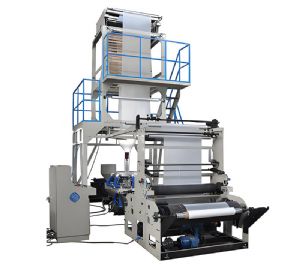
Blown Film Machine
Key factors affecting achievable film thickness range include the extruder's screw design (compression ratio and mixing), the die gap (typically 0.5-2.5 mm), and the draw-down ratio (DDR) which is the ratio of die gap to final thickness. Higher DDR allows thinner films but may cause melt fracture or orientation imbalance. For thin films (≤20 µm), a low BUR (2.0-2.5) and high haul-off speed are used to stretch the bubble; however, bubble stability becomes challenging. For thick films (≥150 µm), a high BUR (3.5-4.5) and lower speed are preferred to maintain bubble integrity. The resin's melt flow index (MFI) also matters – high MFI (low viscosity) facilitates thin film production, while low MFI (high viscosity) is better for thick films. Additives like slip agents and anti-block improve handling of thin films. Temperature profile along the barrel and die must be carefully tuned: higher temperatures reduce melt viscosity, allowing thinner films but risking degradation. Cooling capacity (air ring and IBC) must match the heat to be removed – thicker films require more cooling because they retain more heat. Additionally, the winding tension must be adjusted to avoid stretching or crushing thin films.
Measurement and control of film thickness: online gauges use either beta radiation (for density-independent measurement) or near-infrared (for layer-specific in multi-layer films). The gauge scans across the width, generating a profile that shows high and low spots. The AGC system then activates heating or cooling of individual die bolts to expand or contract the gap locally, correcting the profile. For multi-layer films, each layer's thickness can be controlled via its extruder output; however, overall gauge control remains critical. Offline quality control uses a micrometer or optical gauge to verify samples. Regular calibration of the gauge with standard films ensures accuracy. Operators monitor thickness trends on the HMI and adjust setpoints as needed. In recent years, thickness control has been enhanced by machine learning algorithms that predict gauge variations based on process parameters and automatically adjust settings. This reduces operator intervention and improves consistency. Ultimately, achieving the desired thickness range with high uniformity requires a holistic approach combining machine design, process control, and operator skill. Manufacturers specify a nominal thickness with a tolerance band; meeting these specs is key to customer satisfaction and cost competitiveness.
