Advanced Melt Pump (Gear Pump) Feeding System for Pressure Stability and Output Consistency 2026
A melt pump (gear pump) is a positive displacement device installed between the extruder and the die to provide a steady, pulsation-free flow of molten polymer. Unlike the extruder screw, which can have output fluctuations due to screw rotation and feed variations, the melt pump decouples the extrusion pressure from the screw speed, ensuring a constant volumetric flow to the die. This results in significantly improved thickness uniformity (gauge variation reduced by 50-70%), stable bubble, and better film quality. The pump consists of two meshing gears (driver and idler) that trap polymer in the gear teeth cavities and transport it to the discharge port. The pump speed is controlled independently by a VFD, and it maintains the set flow rate regardless of upstream pressure variations (within limits). The pump also pressurizes the melt to overcome the die resistance, allowing the extruder to operate at lower backpressure, which reduces melt temperature and energy consumption. In summary, the melt pump is a key component for high-quality film production. Its benefits include improved gauge uniformity, reduced surging, and the ability to increase output. The pump must be properly sized (displacement) and controlled to achieve these benefits. The operator should monitor the pump's inlet pressure (to avoid cavitation) and discharge pressure (to ensure adequate die pressure). Regular maintenance (gear inspection, seal replacement) is essential for long-term reliability. In conclusion, the melt pump is a valuable upgrade for any blown film line, delivering superior flow stability and film quality.
The sizing of a melt pump is based on the required output and the melt density. The pump displacement (cc/rev) is chosen such that the pump runs at 30-80% of its maximum speed for the target output range. Too small a pump runs too fast, causing wear; too large runs too slow, causing output pulsations. The pump's inlet pressure must be maintained above a minimum (typically 30-70 bar) to prevent cavitation, which causes flow fluctuations. A pressure transducer upstream of the pump monitors inlet pressure; if it drops, the extruder speed is increased or the pump speed decreased. The pump's discharge pressure is determined by the die resistance; the pump can generate up to 300-400 bar. In practice, the pump is controlled by a cascade loop: the outer loop sets the pump speed based on the desired output, and the inner loop maintains the inlet pressure by adjusting the extruder speed. In conclusion, advanced melt pump feeding systems provide precise flow control, enabling consistent film thickness and quality, and are essential for high-end blown film production.
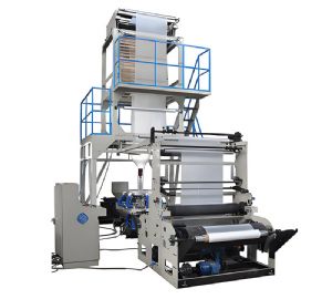
Blown Film Machine
Key melt pump parameters: Displacement (cc/rev): based on output and speed range. Inlet pressure: 30-70 bar minimum to avoid cavitation. Discharge pressure: up to 400 bar. Speed range: 30-80% of max. Control: cascade loop (pump speed + extruder speed). Sizing formula: Pump speed (RPM) = (Output kg/h × 1000) / (Density (kg/m³) × Displacement (cc/rev) × 60 × Efficiency). Efficiency: typically 0.8-0.9. In practice, the operator should monitor the inlet pressure and adjust the extruder speed if it drops. Regular maintenance includes gear inspection and seal replacement. In conclusion, the melt pump is a key component for achieving superior flow stability and film quality.
