Advanced IBC Manifold Design and Air Distribution for Uniform Internal Cooling 2026
The IBC manifold is a critical component that distributes the internal cooling air inside the bubble. The manifold is a tube with multiple outlets (nozzles or slots) positioned near the frost line. The design must ensure uniform air distribution around the circumference to avoid asymmetric cooling, which causes gauge bands. The manifold's geometry – number of outlets, their diameter, orientation, and the tube's cross-section – determines the uniformity. CFD simulations are used to optimize the manifold design for a given bubble diameter and internal air flow. The goal is to achieve a uniform velocity and temperature profile at the outlets. The pressure drop across the manifold must be balanced; a manifold with a tapered cross-section can maintain constant velocity along its length. The outlets are often angled tangentially to promote a swirling flow that enhances heat transfer and stability. The manifold is made of stainless steel or aluminum, with a smooth surface to prevent contamination. In summary, the manifold design is a precision engineering task that directly affects the film's gauge uniformity. A well-designed manifold delivers symmetric cooling, reducing gauge bands by 50% or more. The operator should regularly inspect the manifold for blockages or damage; any asymmetry in the bubble shape indicates a manifold issue.
The air distribution from the manifold interacts with the external air ring cooling. The combined cooling must be balanced to achieve a uniform frost line. The manifold's height relative to the die and frost line is adjustable; the optimal position is just below the frost line, where the film is still molten. The internal air flow is typically lower than the external flow, but it has a significant effect on the temperature gradient. The use of a multi-zone manifold, where different sections can be independently controlled, allows fine-tuning of the cooling distribution. This is particularly useful for wide films where edge cooling may differ from center cooling. In practice, the operator can adjust the internal air flow and the manifold height to achieve a symmetrical bubble. The use of thermal imaging can help visualize the temperature distribution and verify the manifold's performance. In conclusion, the IBC manifold is a key enabler of uniform internal cooling. Its design and maintenance are essential for achieving high gauge uniformity and film quality.
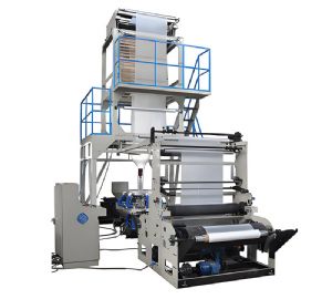
Blown Film Machine
Key manifold design parameters: – Number of outlets: typically 4-8, depending on bubble diameter. – Outlet diameter: determines velocity and flow distribution. – Outlet angle: tangential (for swirl) or radial. – Manifold cross-section: tapered to maintain constant velocity. – Height adjustment: relative to die and frost line. – Material: stainless steel, smooth finish. – Cleaning access: for maintenance. CFD simulation: – Model internal air flow and heat transfer. – Evaluate velocity and temperature uniformity at outlets. – Optimize outlet spacing and diameter. – Validate with thermal imaging. – Iterate design for best uniformity. Operational adjustments: – Internal air flow: adjust based on frost line. – Manifold height: fine-tune for optimal cooling. – Check for symmetry: if bubble tilts, adjust manifold. – Clean manifold regularly to prevent blockages. In practice, the manifold is often overlooked, but its condition directly affects film quality. Regular inspection and cleaning are essential. In conclusion, the IBC manifold is a precision component that requires careful design and maintenance to achieve the full benefits of internal bubble cooling.
