Advanced Die and Feed Block Design for High-Layer-Count Co-extrusion Blown Film 2026
The die and feed block are the heart of a multi-layer co-extrusion blown film line, determining the layer distribution and uniformity. For high-layer-count systems (5-layer and above), the die design becomes increasingly complex. The two main types are feed block dies (combining layers before the die) and multi-manifold stack dies (combining near the die exit). Feed block dies are simpler and less expensive, but they require that the viscosities of all layers be closely matched because the layers flow together through a common channel. Multi-manifold dies, where each layer has its own spiral mandrel, allow independent temperature and flow control, which is essential when processing resins with different melting points (e.g., PE and PA). The die's internal flow channels must be designed to distribute each layer uniformly around the circumference without stagnation. Stagnation zones can cause polymer degradation, leading to gels and black specks. The die material is typically tool steel or stainless steel, with a polished surface to reduce adhesion. The die is heated with multiple zones to maintain temperature uniformity within ±1°C. The die gap (the annular opening) is set by the die lip, which can be adjusted globally or locally using thermal bolts. For high-layer-count dies, the number of thermal bolts is increased to provide finer profile control. In summary, the design of the die and feed block is a specialized field that requires advanced engineering and simulation. The use of computational fluid dynamics (CFD) is essential to optimize the flow distribution and predict potential instability. The die must be manufactured with high precision to ensure that the layers remain distinct and uniform.
The feed block design for multi-layer co-extrusion involves stacking plates, each with a channel for one layer, to form the complete flow path. The channel dimensions (width, height, and length) are calculated based on the flow rate and viscosity of each layer. The goal is to balance the pressure drop across all channels so that the layers exit the feed block at the same velocity and pressure. If the pressure drops are unbalanced, the layers will have different velocities, causing interfacial instability. Adjustable restrictor bars can be added to fine-tune the balance. The feed block is heated to the melt temperature; thermal expansion must be accounted for to prevent distortion. The feed block is typically located before the die; for very wide films, the feed block may be integrated with the die. The feed block's design also includes a transition from the rectangular channel to the annular die; this transition must be smooth to avoid flow separation. In multi-manifold dies, each mandrel is designed with spiral channels that distribute the melt; the number of spirals and their geometry are optimized using CFD. The mandrels are stacked, and the layers are combined at the die lip. This design provides excellent layer uniformity but is more expensive and requires careful alignment. In practice, the die and feed block are the most expensive components of the line, often costing 20-30% of the total line price. Their maintenance involves regular cleaning (using purging compounds and disassembly) and inspection for wear. Any scratches on the die lip cause permanent die lines. In conclusion, the die and feed block are the enablers of multi-layer co-extrusion. Their design must be tailored to the specific layer structure and resins. By using advanced simulation and precision manufacturing, converters can achieve the high level of layer uniformity and stability required for premium films.
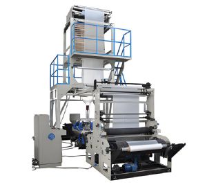
Blown Film Machine
Key design parameters for feed block: – Channel width and height: based on flow rate and viscosity. – Channel length: determines pressure drop; must be balanced across layers. – Restrictor bars: for fine-tuning pressure balance. – Heating zones: to maintain temperature uniformity. – Material: stainless steel with polished surfaces. – Transition to die: must be smooth and gradual. Key design parameters for multi-manifold die: – Number of spiral mandrels: equals number of layers. – Spiral geometry: channel depth, taper, and number of turns. – Layer combination point: near die lip. – Independent heating zones for each mandrel. – Thermal bolts for profile control. – Die gap: adjustable globally and locally. CFD simulation: – Use to model flow distribution and pressure drop. – Evaluate interfacial velocity matching. – Optimize channel geometry to minimize stagnation. – Predict thermal profile. – Validate with physical measurements. Maintenance: – Regular purging with cleaning compounds. – Periodic disassembly for manual cleaning. – Inspect die lip for scratches; polish if needed. – Check bolt heater resistance and calibration. – Verify mandrel alignment. In practice, the die and feed block are the defining components of a multi-layer line. Their design and maintenance directly impact film quality and production efficiency. Investment in high-quality dies and regular professional maintenance is essential for achieving consistent, high-quality multi-layer films.
