Advanced Component Selection and Integration for High-Performance Blown Film Equipment 2026
Selecting and integrating the right components for a blown film line is crucial for achieving the desired output, quality, and reliability. The extruder motor must be sized for the torque required at the maximum screw speed and melt viscosity. Typically, a gearbox with a ratio of 10-20:1 is used to match the motor speed (1500 RPM) to the screw speed (30-120 RPM). The motor should be a high-efficiency AC induction motor with a VFD for speed control. The gearbox must have a service factor of at least 1.5 to handle peak loads and shock. The heater bands on the barrel and die must have sufficient watt density to heat the steel mass within a reasonable time; typical heater power is 0.5-1.0 kW per zone. The thermocouples (J or K type) must have a fast response and be positioned close to the melt to provide accurate feedback. The pressure transducers (strain gauge type) must be rated for the maximum melt pressure (up to 500 bar) and have a high accuracy (±0.5%). The screen changer can be manual, hydraulic, or continuous; the selection depends on the line's output and the required filtration fineness. The cooling system includes the air ring blower (centrifugal, with VFD) and, if used, the IBC chiller and blower. The thickness gauge is a critical component; beta gauges are reliable but require radioactive source licensing; X-ray gauges are faster but more expensive; NIR gauges can measure layer thickness in multi-layer films. The winder can be surface or center winding; center winding provides better tension control but is more complex. The control system's PLC must have sufficient processing power and memory for all the control loops, and the HMI should be user-friendly with graphical displays. In summary, each component must be selected based on the specific requirements of the line, and they must be compatible with each other in terms of communication protocols and physical interfaces.
Integration of the components is as important as their individual selection. The control system must be configured to communicate with all drives, sensors, and actuators via a common fieldbus (e.g., Profibus, Profinet, EtherNet/IP). The PLC must be programmed with interlocks to prevent unsafe conditions (e.g., melt pressure too high, temperature too high). The HMI should provide clear alarm messages and trend charts for troubleshooting. The drive parameters (acceleration, deceleration, speed limits) must be coordinated to ensure smooth startup and shutdown. The heater controllers must be tuned to avoid temperature overshoot. The thickness gauge must be integrated with the AGC system, with appropriate filtering and deadband. The winder's tension control must be slaved to the line speed to maintain constant tension. The integration also involves the safety system: emergency stops, safety relays, and light curtains must be connected to the PLC to shut down the line in case of an emergency. The entire system should be tested during the factory acceptance test (FAT) and then again on-site. In summary, the integration of blown film equipment is a complex engineering task that requires expertise in electrical, mechanical, and software engineering. A well-integrated line operates seamlessly, with all components working in harmony to produce consistent film quality. Conversely, poor integration leads to frequent alarms, production stops, and high scrap rates. Therefore, it is advisable to work with a supplier who offers complete system integration, rather than assembling components from multiple vendors. In conclusion, the selection and integration of blown film equipment components are the foundation of a reliable and efficient production line. By carefully choosing each component and ensuring they are properly integrated, converters can achieve high uptime and consistent product quality, maximizing the return on their investment.
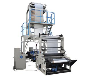
Blown Film Machine
Key component specifications: – Motor: power rating (kW), torque (Nm), speed range, insulation class. – Gearbox: ratio, service factor, bearing life, oil capacity. – Heater bands: watt density, voltage, diameter, length, and material (ceramic, cast aluminum). – Thermocouples: type, accuracy, response time, sheath material. – Pressure transducers: range, accuracy, output signal (4-20 mA). – Blower: flow rate (m³/h), pressure (Pa), motor power, material of construction. – Gauge: type (beta, X-ray, NIR), scan speed, accuracy, calibration method. – Winder: type (surface, center), max roll diameter, tension range, number of stations. – PLC: processor speed, memory, I/O count, communication ports. – HMI: screen size, resolution, graphics capability, alarm handling. In addition, the supply voltage and frequency must match the local utility. The components should be from reputable brands with good after-sales support. The integration should include a comprehensive wiring diagram and a list of all spare parts with part numbers. Proper documentation is essential for troubleshooting. In conclusion, the selection and integration of blown film equipment is a meticulous process that requires attention to detail. Investing in high-quality components and professional integration services ensures a reliable, high-performance production line that will serve for many years.
